Retro Shaders with WebGL
Introduction
In this article, I'm going to show you how to reproduce "retro" visual effects as seen in the "8-bit" musical levels from Rayman Legends. If you have never heard of Rayman Legends or want to see in action the visual effects, you can watch this video showing all the 8-bit music levels (warning: spoilers!).
All of these visual effects are post-processing effects. Meaning that we take a fully drawn image and apply modifications on it.
For better performances, we will be leveraging the GPU using a fragment shader (also known as pixel shader). If you need to brush up on what's a shader or how to write GLSL shaders, you should check-out this great fragment shader introduction by Toby Schachman.
Note that for all the shader examples in this article, you can actually edit the GLSL code on the right and immediately see the result on the left (live WebGL preview). (The live-editing currently does not tell you about compilation errors though, so make sure to double-check your code when nothing happens!)
Original Image
We will be using the same reference image for the entire article. It's in-game screenshot taken from the first world (image credits to Ubisoft).
Before diving into the fragment shaders writting part, let's take a look at the pipeline we're using to render images.
We get handed by the game a fully drawn frame Texture0.
As mentioned earlier, we keep things simple and use a static screenshot.
We then draw that texture onto a quad (two triangles) that matches the size of the viewport (screen). We do so by using a simple vertex shader that
maps the vertex positions to screen-space coordinates. We also compute the texture coordinates UV and send them over to the fragment shader.
The texture coordinates correspond to each pixel/fragment position in the texture (varying from 0.0 to 1.0).
Low-Resolution
For this effect, we want visibly less fragments (pixels) in our final image. You can picture it as resizing down some image and zooming-in so that it fits our original screen size.
There are many ways to do image scaling. In our case, we want to keep the granularity of the pixels, and avoid any smoothing (and this is fortunately easier to achieve).
The solution presented here is a good tradeoff between performance and aesthetics.
We take the color of a given pixel, and stretch that color to larger area.
To do so, we transform the texture coordinates into a smaller set of discrete values.
This is exactly what is being done with the pos vector.
In the code above, we use a new float uniform Resolution which value is equal to the ratio width / height of the viewport.
The vertical resolution ny is computed so that each pixel ends up looking like a square. You can try to use the same value for
nx and ny to see the pixels take a rectangular shape (same ratio as the viewport).
To give it a better look, we also floor() the result in order to get the pixels well-aligned with the screen borders.
Depending on the nx value, the pixels won't necessarily be squares, but they won't noticeably look like rectangles either.
Division
In one of the musical level, the screen suddenly divides itself into smaller identitical screens.
A naive approach for this effect would be to render the texture mulitple times at a smaller scale and different locations.
But we can do better using a single texture and the mod() function (Modulo Operation).
In the example above, we want a 2 by 2 division.
With n = 2, mod(UV,1.0/n) will transform the coordinate space from [0.0, 0.5] to [0.0, 0.5] and
[0.5, 1.0] to [0.0, 0.5].
If we stopped here, we would get the screen division as expected, but each division would only contain the bottom-left half of the texture.
By multiplying the result by n, we transform back the coordinate space to its intended [0.0, 1.0] interval.
Barrel Distortion
The barrel distortion is actually used in the first 8-bit musical level and gives the feeling of running around some never-ending circular structure.
It's worth pointing out that this effect comes handy in fields such as virtual reality. Lenses used in head-mounted-displays such as the Oculus Rift provide a wide field of view for better immersion. But such lenses also affects what you will see with a pincushion distortion. The barrel distortion is then used on the rendered image to compensate and see things undistorted.
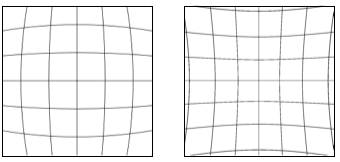
Barrel Distortion ~ vs ~ Pincushion Distortion
I already see you coming with a question... what's the math behind this? Looking at the shader, there's one line where magic happens:
vec2 pos = UV; // (0)
pos -= vec2(0.5, 0.5); // (1)
pos *= vec2(pow(length(pos), distortion)); // (2) - aka magic happens!
pos += vec2(0.5, 0.5); // (3)
Let's ignore the pow() function for now and substitute (2) with the expression below:
pos *= vec2(length(pos)); // (2)
Step by step:
We begin by changing the coordinate space from [0.0, 1.0] to [-0.5, 0.5]. The center of the picture now becomes (0.0, 0.0).
We can then use the vector norm length(pos) to easily compute how far is each position compared to the origin.
Each position gets multiplied by its distance to the origin and is then shifted back by 0.5.
For y = 0, the way the x coordinate varies can be visualized as follow:
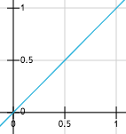
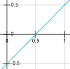
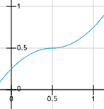
From left to right: (0), (1), (2) and (3)
(3): x' = (x - 0.5) * abs(x - 0.5) + 0.5 , for x in [0.0, 1.0]
Visually speaking, we are changing the sampling rate of the texture.
The left-most plot shows the original coordinate space with no distortion.
UV.x increases linearly and we sample the texture at a fixed interval (no distortion).
With the distortion applied to the original position,
we now have a variable sampling interval as seen in the right-most plot.
As you can notice, the final coordinate space changes from [0.0, 1.0] to [0.25, 0.75]. Meaning that we are losing parts of the texture that are close to the edges.
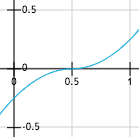
This is where the pow() function we omited in the first place comes handy.
We can indeed use it as a way to extend the original bounds,
and this without losing too much of the distortion.
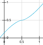
x' = (x - 0.5) * pow(abs(x - 0.5), 0.5) + 0.5 for x in [0.0, 1.0]
If we now consider all the values of y, the x coordinate variation becomes:
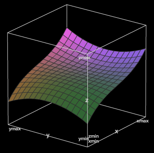
x' = z = (x - 0.5) * pow(length(vec2(x - 0.5, y - 0.5)), 0.5) + 0.5
x, y, z in [0.0, 1.0]
The plot for y is very similar to the one above.
Try playing around with the values and math to see how the distortion changes.
You can also use Texture1 which will display a grid instead of the regular screenshot.
Extra note concerning performance. Since all these per-fragment distortion computations are expensive, a way to optimize this effect would be to use a distortion mesh as a rendering target instead of a regular quad. We leverage per-frame and per-fragment computations with a pre-computed mesh built once and re-used every frame.
Noisy Signal
In a distant past, older TVs would display a white noise signal when there was no transmission signal from the antenna (good old days!). In order to generate a white noise image, each pixel has to be set using a random intensity.
GLSL does not provide a random number generator function, but there are multiples ways to work-around this. One way is to use a texture that acts as a random value generator. Another solution consists in using a hash function exploiting floating point approximation errors.
In this shader, we use a well-known one-liner hash function rand(),
taking a vec2 as an input and returning a random value between [0.0, 1.0].
For each fragment, we get a random intensity based on the UV value.
If we stopped here, we would always get the same value per fragment and the white noise image would be static.
In order to get some fancy animation, we introduce a Time uniform that increases every frame (60 FPS).
By multiplying the texture coordinates by a value changing over time,
we will grab a different intensity value per pixel at a given frame.
Here we use sin(Time) as the factor. Negative values are not an issue since texture coordinates will automatically
wrap to something between [0.0, 1.0].
Lastly, we merge the original texture color with the white noise using the mix() function.
You can change the way colors get mixed by changing noise_intensity (1.0 -> noise only).
Game Boy Palette Mapping
This effect is not actually in the game, but I decided it would be cool to present it anyway. (The actual shader they use only consists in adding a yellow-ish tone to the final picture).
The principle is to map a given input color space into a limited subset of colors (palette). Since the original Game Boy (and we are talking about the grey brick here) only had 4 colors, this will be our target palette:
1
2
3
4
For each fragment color, we return (bucketize) one of the four target colors by measuring then choosing the smallest difference between the two color.
Since colors are just vectors, this is done by computing the length() of the difference between two colors.
Note that we also apply a positive gamma correction to the original texture color for better results. Check out the gamma correction page on Wikipedia for more details.
Old CRT Monitor Effect
Let's talk about old TVs again. The technology used back then was a cathode ray tube. If you looked closely, you could see faint horizontal lines on the monitor. And this is exactly what this last shader is about. How do we go about drawing horizontal bars going accross the screen, as would an old CRT monitor?
Let's take a closer look at the following expression: abs(sin( UV.y * 100 + Time * 5.0)) * 0.08;.
This can be rewritten as the following: A * abs(sin(B * y + C)).
abs(sin(x))
-
A is the amplitude. The
abs(sin())function will return a value between [0.0, 1.0] that we then scale by A. -
TWO_PI / B is the period. The higher B the faster
abs(sin())will oscillate between [0.0, 1.0] (increased frequency). -
C is the phase shift. We move the repetition pattern (phase) of our sinusoidal by a some value. For instance, with x = 0.0, we originally have sin(x) == 0.0. By adding C, we now have sin(x + C) == sin(C). Thus changing the origin from (0.0, 0.0) to (-C, 0.0), creating a phase shift (displacement).
Let's put things in context and go back to our shader. More specifically, this line that we are going to deconstruct:
color -= abs(sin(UV.y * 100.0 + Time * 5.0)) * 0.08; // (1)
For a better understanding of what is going on, I would recommend commenting the line right below.
Overall, this operation will reduce the color intensity by a value within [0.0, 0.08]. Since we use a periodic function, we can expect gradient patterns repeating over and over (colors becoming lighter, then darker, and so on...).
The abs(sin()) call takes UV.y as an input.
This means that the variation in color intensity depends on the vertical coordinate of the fragment.
This also implies that our gradients will be spreading vertically too.
Coupled with a really short period UV.y * 100.0, the number of successive gradients will increase drastically.
Again, we could just be satisfied with a static image and stop here.
But since we want some fancy, we also use a phase shift by adding Time * 5.0.
With a phase shift changing over time, it adds an additional vertical displacement to the gradients (here top to bottom).
The second line is really similar to the one above, but uses different parameters within the function:
color -= abs(sin(UV.y * 100.0 + Time * 5.0)) * 0.08; // (1)
color -= abs(sin(UV.y * 300.0 - Time * 10.0)) * 0.05; // (2)
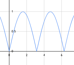
Turns out that we can achieve some interesting patterns by combining the two signals:
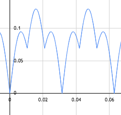
abs(sin(100.0 * x)) * 0.08 + abs(sin(300.0 * x)) * 0.05
In the end, we have moving horizontal lines made out of vertical gradients, simulating the CRT beam deflection.
I strongly encourage you to tinker around with the values and see how things change as you do so.